Y Block
Power Potential
Please note that this page is still under construction!
Intake Air
Flow: A predictor of power
One of the main concerns of the potential Y
Block builder is: “How much power can I expect to obtain from my Y Block?” This
question is difficult to answer, since each Y Block builder envisions a
different use and a different choice of components when building their engine.
One useful tool that can be used to determine the potential power output of the
completed Y Block project is to compare it with other engines, whose power
output capabilities are widely known.
The maximum power potential of any engine
is limited, ultimately, by how much power-producing air/fuel mixture can be
processed by the four cycles of the engine: Intake, Compression, Power, and
Exhaust. Perhaps the single most critical piece of data in this very complex
calculation is the amount of air/fuel mixture that can be passed through the
intake port.
Increasing an engine’s displacement will
enable it to produce a given level of power at a lower RPM, but ultimately, it
is the flow capacity of the intake tract that will limit peak power, regardless
of the swept volume of the cylinders.
This section will present the maximum
theoretical capabilities of Y Block power output and compare them with the same
theoretical capabilities of other engines. A rough idea of how a Y Block would
compare with another in a similar state of tune can then be ascertained.
Many other factors need to be considered
before one can use the presented data to predict the specific horsepower output
of their own engine. First of all, the data represents a theoretical maximum,
and few builders will be preparing their engines to produce the maximum amount
of horsepower. Secondly, this data only considers the flow capability of the
intake port. The flow capability of the rest of the intake tract, the manifold,
carburetor(s), and filters, is not considered. Nor is the efficiency of the
combustion chamber or the flow of the exhaust system considered directly, which
also has an impact on power output.
It is assumed that each engine is able to
achieve the RPM level needed to achieve these flow figures.
Let us consider how this might work by
relating it to a real world example.
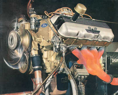
The SOHC 427 on the dyno: Don’t we all appreciate a better idea?
From the chart below, we see that the SOHC
427 Ford engine had an intake flow rate of 355 CFM, for a potential power
rating of 730 horsepower. We know that the SOHC with a single 4v carburetor,
was rated at 617 horsepower and with dual 4v carburetors, at 667 horsepower.
Allowing for the loss incurred by the restrictions of the carburetors and
intake manifold, the losses incurred by the exhaust system and the tuning level
of the installed camshafts, we see that these figures are pretty close to our
estimated power levels. It is also interesting to see that such a large engine
loses 50 hp due to the restriction imposed by the single 4v.
For our Y Block, we can use these figures
several ways. For example, consider the famous Y Block build published in a
1971 issue of Popular Hotrodding. The 312 that was tested in this article
produced only 258 horsepower. Where did the other 100 horsepower go, if the
power potential figure is correct in the chart below? First, we must consider
the camshaft, which while suitable for street high performance, did not
maximize the total flow capabilities of the head. Second, we should consider
the intake manifold, and Offenhauser 3x2 unit. We must factor in the
restriction of 3 small carburetors and the construction details of a multi-carb
Y Block manifold, the flow of which is restricted by carb down passages
blocking the upper manifold plane, through which they pass. Also, in my
opinion, the Offy 3x2 is not likely to flow as well as an Edelbrock 573.
finally, consider the exhaust side flow losses, and the 312 build described in
the article meshes fairly close to the power potential figure in the chart
below.
It is also apparent that the Y Block, based
on intake flow, was more than able to match up with its rival of the 50s, the
small block bowtie motor. Comparing 283 and 327 heads with the ECZ-G head, the
figures are quite close, at least on the intake side. Most engine designers
today believe that exhaust flow should be between 75% and 80% of intake flow to
allow for adequate exhaust and yet permit a large enough intake valve. (This is
because, in real operation, intake flow is sustained by atmospheric pressure
alone, whereas exhaust flow is aided by cylinder pressure, which is about 5 or
6 times above atmospheric during much of the exhaust cycle.)
Deriving
and using the figures
There
are many factors that contribute to an engine’s power capabilities, but intake
flow is one of the major ones, just as the closing point of the intake valve is
the key event to determining a camshaft’s characteristics, all other things
being equal. The “power potential” data of these tables is based on the factor
of .25714, the commonly accepted number for converting intake airflow @ 28
inches of water to horsepower. (To use this figure, multiply it by the number
of cylinders to obtain a power estimate.)
As a rough estimate, it is feasible to
multiply the power potential figure by 10% when using methanol (alcohol) as a
fuel.
This information can also be used to estimate
the amount of power that may be expected from the installation of a
supercharger or turbocharger. By using the level of forced induction, measured
as pressure, and recalculating the flow rate based on the new pressure
differential, one can obtain a prediction of supercharged power.
To recalculate the flow rate, use this
formula:
Supercharged CFM = Natural CFM x √(New pressure ÷ Old pressure)
Then, multiply this new flow rate by .25714 and by the
number of cylinders to obtain the supercharged power potential.
Example:
Our Y Block, with ECZ-G heads, flows 175 CFM on the
intake side, for a power potential of 360 horsepower. We would like to know the
power output that could be expected if we installed a supercharger providing 6
psi of boost.
Calculation:
6 psi of boost pressure is approximately equal to 12
inches of H2O pressure, so we would need to calculate the new flow rate based
on a pressure of 40 inches of H2O, rather than 28 inches. Using the formula
above:
Superchd. CFM = 175 x
√(40
÷ 28)
Superchd. CFM = 175 x
√1.43
Superchd. CFM = 175 x 1.2
Superchd. CFM = 209
Multiplying this figure by the power potential factor
and the number of cylinders, we find that our Y Block, supercharged @ 6 psi of
boost, has a power potential of 430 horsepower. Considering that on the street,
our Y Block produces only 300 horsepower naturally aspirated, due to flow
restrictions of the intake tract, exhaust tract, and other factors, we could
say that our street Y Block would actually see and increase to about 360 horsepower:
Actual schd horsepower = (actual NA hp ÷ potential NA
hp) x potential schd hp
Or:
359 = (300/360) x 430
You can do other interesting things with this
information that will increase your appreciation and understanding of engines,
in general. For instance, consider that naturally aspirated Offenhauser engines
running at Indianapolis in the mid 60s produced about 425 to 450 horsepower. If
one factors out the use of methanol fuel by subtracting about 10% of this
power, that would mean that these Offys were flowing about 400 CFM on the
intake side, a very impressive figure for an engine that was designed by the
seat of the pants, rather than by flow benches and scientific calculations.
|
Head Type |
Lift |
Intake Valve Size |
Intake Flow (CFM @ 28” of H2O) |
Exhaust Valve Size |
Exhaust Flow (CFM @ 28” of H2O) |
Power Potential (hp) |
Comments |
|
239 |
.500 |
1.64 |
|
1.51 |
|
|
|
|
272 |
.500 |
1.78 |
|
1.51 |
|
|
|
|
|
.500 |
|
|
1.51 |
|
|
|
|
ECZ-G |
.500 |
1.92 |
175 |
1.51 |
125 |
360 |
|
|
ECZ-G |
.500 |
1.94 |
215 |
1.60 |
152 |
442 |
John Mummert’s Street Port |
|
ECZ-G |
.550 |
2.02 |
233 |
1.60 |
182 |
479 |
John Mummert’s Race Port |
|
Aluminum Prototype |
.600 |
1.94 |
270 |
1.50 |
217 |
555 |
Other Ford engines
|
Head Type |
Lift |
Intake Valve Size |
Intake Flow (CFM @ 28” of H2O) |
Exhaust Valve Size |
Exhaust Flow (CFM @ 28” of H2O) |
Power Potential (hp) |
Comments |
|
289 |
.500 |
1.78 |
165 |
1.45 |
107 |
339 |
|
|
289HP |
.500 |
1.78 |
170 |
1.45 |
121 |
350 |
|
|
302 |
.500 |
|
154 |
|
107 |
317 |
E7TE |
|
351W |
.600 |
1.84 |
177 |
1.54 |
142 |
364 |
|
|
351C |
.600 |
2.04 |
230 |
1.65 |
172 |
473 |
2V |
|
351C |
.600 |
2.19 |
284 |
1.71 |
154 |
584 |
4V D1ZE |
|
390 |
.600 |
2.04 |
261 |
1.57 |
166 |
536 |
Std. FE pass head |
|
428CJ |
.600 |
2.09 |
243 |
1.65 |
174 |
500 |
427 Lo Riser & 428 CJ |
|
427HR |
.600 |
2.19 |
246 |
1.73 |
165 |
506 |
Hi Riser C4AE-G |
|
427MR |
.600 |
2.19 |
296 |
1.73 |
177 |
609 |
Medium Riser |
|
427TP |
.600 |
2.25 |
308 |
1.73 |
166 |
634 |
Tunnel Port |
|
427 SOHC |
.600 |
2.25 |
355 |
1.90 |
248 |
730 |
The “Cammer” |
|
429 |
.600 |
2.08 |
272 |
1.66 |
177 |
560 |
|
|
429CJ |
.600 |
2.25 |
331 |
1.72 |
201 |
681 |
Cobra Jet |
|
429 Boss |
.600 |
2.28 |
379 |
1.90 |
225 |
780 |
|
AMC Engines
|
Head Type |
Lift |
Intake Valve Size |
Intake Flow (CFM @ 28” of H2O) |
Exhaust Valve Size |
Exhaust Flow (CFM @ 28” of H2O) |
Power Potential (hp) |
Comments |
|
401 |
.500 |
2.02 |
213 |
1.68 |
185 |
439 |
Part #8120126 |
Buick Engines
|
Head Type |
Lift |
Intake Valve Size |
Intake Flow (CFM @ 28” of H2O) |
Exhaust Valve Size |
Exhaust Flow (CFM @ 28” of H2O) |
Power Potential (hp) |
Comments |
|
401 |
.600 |
1.87 |
195 |
1.50 |
120 |
402 |
“Nailhead” |
|
455 |
.500 |
2.00 |
187 |
1.62 |
166 |
390 |
|
|
Stage I |
.500 |
2.13 |
230 |
1.75 |
187 |
473 |
Part 1234602 |
|
Stage II |
.500 |
2.13 |
230 |
1.75 |
213 |
473 |
|
Chevrolet Engines
|
Head Type |
Lift |
Intake Valve Size |
Intake Flow (CFM @ 28” of H2O) |
Exhaust Valve Size |
Exhaust Flow (CFM @ 28” of H2O) |
Power Potential (hp) |
Comments |
|
283 |
.500 |
1.72 |
166 |
1.50 |
166 |
341 |
|
|
327 |
.500 |
1.94 |
175 |
1.50 |
166 |
361 |
|
|
400 |
.500 |
1.94 |
175 |
1.60 |
171 |
361 |
|
|
F.I. |
.600 |
2.02 |
185 |
1.60 |
171 |
380 |
|
|
Turbo |
.700 |
2.02 |
199 |
1.60 |
175 |
410 |
|
|
Std. |
.600 |
2.06 |
308 |
1.72 |
201 |
634 |
Oval Port 396 |
|
Hi Po |
.700 |
2.19 |
332 |
1.72 |
201 |
683 |
Rectangular Port |
|
Open |
.700 |
2.19 |
341 |
1.88 |
213 |
702 |
Open chamber cast
iroiron |
|
Open |
.700 |
2.19 |
337 |
1.88 |
206 |
692 |
Open chamber ZL-1
aluminum |
Chrysler Engines
|
Head Type |
Lift |
Intake Valve Size |
Intake Flow (CFM @ 28” of H2O) |
Exhaust Valve Size |
Exhaust Flow (CFM @ 28” of H2O) |
Power Potential (hp) |
Comments |
|
318 |
.500 |
1.78 |
166 |
1.50 |
130 |
341 |
|
|
360 |
.600 |
1.88 |
190 |
1.60 |
142 |
390 |
|
|
340HP |
.600 |
2.02 |
213 |
1.60 |
142 |
439 |
|
|
W2 |
.600 |
2.02 |
265 |
1.60 |
174 |
545 |
“Economy” |
|
B/RB |
.600 |
2.08 |
284 |
1.75 |
178 |
585 |
“906” |
|
Hemi |
.700 |
2.25 |
356 |
1.94 |
213 |
731 |
|
Oldsmobile Engines
|
Head Type |
Lift |
Intake Valve Size |
Intake Flow (CFM @ 28” of H2O) |
Exhaust Valve Size |
Exhaust Flow (CFM @ 28” of H2O) |
Power Potential (hp) |
Comments |
|
350 |
.500 |
1.88 |
182 |
1.62 |
140 |
375 |
|
|
455 |
.500 |
2.07 |
199 |
1.68 |
149 |
410 |
|
Pontiac Engines
|
Head Type |
Lift |
Intake Valve Size |
Intake Flow (CFM @ 28” of H2O) |
Exhaust Valve Size |
Exhaust Flow (CFM @ 28” of H2O) |
Power Potential (hp) |
Comments |
|
77 |
.600 |
1.92 |
194 |
1.66 |
143 |
399 |
’65 GTO & 421 HO |
|
670 |
.600 |
2.11 |
205 |
1.77 |
194 |
422 |
1967 400 & 428 |
|
6X |
.500 |
2.11 |
212 |
1.66 |
148 |
436 |
76-79 400 |
|
RA III |
.600 |
2.11 |
216 |
1.77 |
172 |
444 |
Ram Air III |
|
5C |
.500 |
2.11 |
222 |
1.77 |
171 |
457 |
75 - all |
|
RA IV |
.600 |
2.11 |
225 |
1.77 |
177 |
463 |
Ram Qir IV |
|
16 |
.500 |
2.11 |
244 |
1.77 |
171 |
502 |
68-69 400 428 |
|
455SD |
.600 |
2.11 |
249 |
1.77 |
161 |
512 |
Super Duty |